Jax' place

Phono amplifiers with tubes

With software for simulation of analogue electronics becoming available I could sit down and tweak the RIAA correction network and also look at other designs found on the net. I use the original design shown here without the correction network. Please note the mistake I did in the schematic, the labels RIAAOUT and RIAAIN should change place, else the networks shown below wouldn't make sense. All resistors used are 0.25W metal film resistors with 1% tolerance. Capacitors are polystyrene in my build but these are no longer available. A good replacement is polypropylene with 1% tolerance but seems to be hard to find nowadays. Illinois Capacitor used to have them. Italian Icel seems to make them. They do not need to be high voltage rated, 63VDC should be good but for us point-to-point wiring junkies, axial lead capacitors are prefered and those are normally 630VDC. All gain figures below are with 5751 tubes.

picture of riaa base schematic
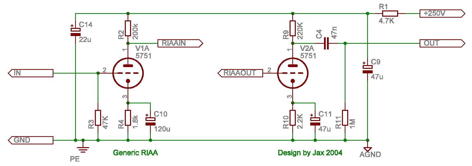
The base schematic used for tweaking.

1. Original design

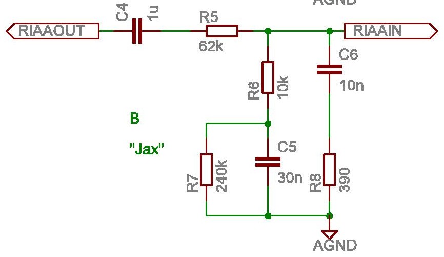
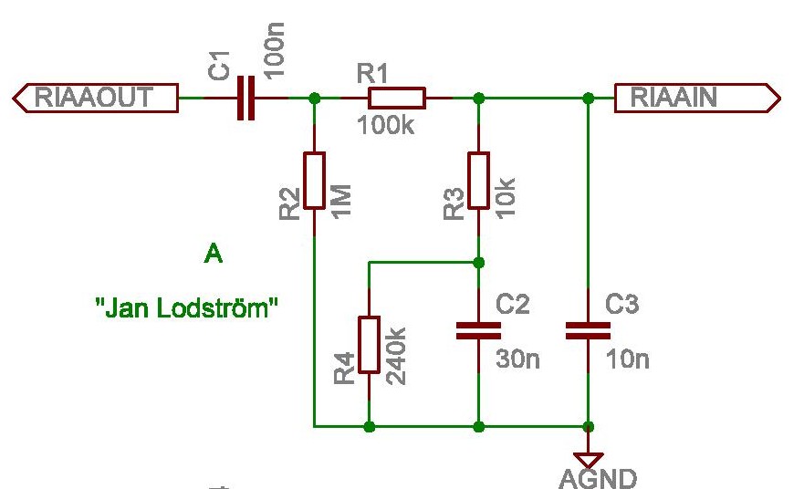
First is about the original design by Jan Lodström. This network deviates around +1dB at 20Hz from the ideal RIAA curve. It's missing the zero at 50kHz but it's easy to add if one wish to but it's not that important.
It has two advantages, there is no need for a separate grid leak resistor on the following stage and C3 slugs the Miller capacitance in it. It uses atandard values, 30nF is two 15nF in parallel and the 240k is from E24 series but two 120k in series can be used. Gain is 48dB at 1kHz.


picture of Lodstrom schematic

2. My own tweak

I changed some resistors and added a resistor to form the 50kHz zero, R8. This zero can be removed by replacing R8 with a wire. Deviation is now down to +0.2dB. Still no unusual values, resistors are within the E24 series and the capacitors are the same. Gain is 50dB at 1kHz.

picture of Jax schematic

3. Tweety

This is a design I found on the web many years ago called Tweety and the designer's name is Maarten. I have tried to find it again but is nowhere to be seen, unfortunately. It deviates no more than +0.2dB at 1kHz but has the disadvantage requiring an extra resistor as grid leak for the following stage. This may cause slightly more noise. It has unusual component values but can be fixed with series and parallel connection of standard values. Gain is 53dB at 1kHz.

picture of Tweety schematic

4. Loekie

This one was found on the same now missing site as Tweety. It's basically the same as Tweety but with slightly different values but with standard value capacitors. It's also missing the 50kHz zero. A separate grid leak resistor is needed here too. Gain is 52dB at 1kHz.

picture of Loekie schematic

5. Scratch

This is a design called Scratch by Triode Dick and is still on the web which can be found here.

picture of Scratch schematic

6. Building hints

Use a regulated power supply for the high voltage. Use 6V DC heater and one side of it must be connected to AGND or you will hear a lot of hum. Connect AGND near the phono input to the chassis and this should be the same point where the separate ground wire from the player should be connected. This is the only point where AGND is connected to the chassis, even if you have a following line stage. The input connectors should be insulated from the chassis and their grounds connected to AGND near stage 1. Note that the output impedance is high so if you are building a separate phono preamplifier, add a cathode follower after stage 2 with its grid connected directly to the plate of stage 2. For stereo, use one tube for both stage 1 and one for both stage 2.